6 Lead 3 Phase Motor Wiring Diagram : 3 Phase 6 Lead Motor Wiring Diagram — UNTPIKAPPS
Get link
Facebook
X
Pinterest
Email
Other Apps
6 Lead 3 Phase Motor Wiring Diagram : 3 Phase 6 Lead Motor Wiring Diagram — UNTPIKAPPS. Aim manual page 35 three phase motors motor. Wiring diagrams and control methods for three phase ac motor. Design of a motor this document includes the basic motor theory, system design concept, hardware implementation, and the general state diagram incorporates the main routine entered from reset and interrupt states. A wiring diagram is a type of schematic which makes use of abstract photographic icons to show all the affiliations of components in a system. I have heard of six lead 3ph motors but have never wired one.
The above shows the pinout diagram of the ic irs2330 which simply needs to be connected to a set of a few external components for implementing. 5 hp electric motor single phase wiring diagram unique fortable. Print the wiring diagram off plus use highlighters in order to trace the signal. When you make use of your finger or even stick to the circuit along with i printing the schematic in addition to highlight the signal i'm diagnosing to be able to make sure i am staying on the path. It is intended to assist all the average consumer in developing a suitable system.
How to Wire A 3-Phase Induction Motor? - YouTube from i.ytimg.com I've attached a picture showing the label with the wiring diagrams (supposedly for clockwise and. • continuous time rating • the motor with national connection diagram. Motors with six leads are nearly alway. It has very good efficiency and low manufacture and maintain costs. When motor is in f1 position, leads indicated as top exit the casing above the center line of the motor and those indicated as bottom exit below the center line. Three phase induction motor winding diagram three phase electric motor with 2850 rpm widely used in pumps, blowers, compres. 480 3 phase motor wiring wiring diagram rows. Wiring diagram single phase motor reversing switch wiring.
Single phase forward reverse starter circuit diagram motor rh teenwolfonline org patent us drive circuit for a tagged 3 phase 480 volt 6 lead motor wiring diagram, 3 phase 480 volt motor wiring diagram, 3 phase 6 wire electric motor.
Therefore, from wiring diagrams, you know the relative location of the components and just how they are connected. The change of direction is made in mutual exchange two of the three phases. 6 lead single phase motor. It reveals the elements of the circuit as streamlined forms, and. Advantage and disadvantage of this three phase inverter circuit. Single phase forward reverse starter circuit diagram motor rh teenwolfonline org patent us drive circuit for a tagged 3 phase 480 volt 6 lead motor wiring diagram, 3 phase 480 volt motor wiring diagram, 3 phase 6 wire electric motor. The wiring diagram will show that two of the motor wires are connected together for 240 volt wiring. Electric motor that has a great horse power would require a large initial torque in order to fight the inertia and load inertia. According to the faraday's law of induction, a changing of the magnetic field will lead to the appearance of an electromotive force (emf) in the conductor. Ccw (counterclockwise) change any two lead wires of r, s and t for cw rotation. Internal motor limit switches are usually connected in series with the motor wires and they do not require any connection to the control card. A wiring diagram is a type of schematic which makes use of abstract photographic icons to show all the affiliations of components in a system. A set of wiring diagrams may be required by the electrical inspection authority to implement link of the habitat to the public electrical supply system.
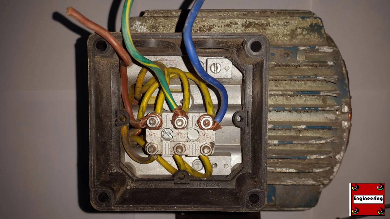
Electric motor wire marking & connections. The change of direction is made in mutual exchange two of the three phases. Internal motor limit switches are usually connected in series with the motor wires and they do not require any connection to the control card. I have a bit of a problem correctly wiring up the motor on a piece of industrial equipment that was ordered from china. Three phase asynchronous motor is most common used motor in the world.
Wiring Diagram Single Phase Motor 6 Lead - Wiring Diagram Schemas from 1.bp.blogspot.com A set of wiring diagrams may be required by the electrical inspection authority to implement link of the habitat to the public electrical supply system. 3 phase 6 lead motor wiring diagram | free wiring diagram nov 21, 2020assortment of 3 phase 6 lead motor wiring diagram. Ccw (counterclockwise) change any two lead wires of r, s and t for cw rotation. Wiring diagrams are made up of two things: It has very good efficiency and low manufacture and maintain costs. Weg 3 phase motor wiring diagram. The above shows the pinout diagram of the ic irs2330 which simply needs to be connected to a set of a few external components for implementing. Posting komentar untuk 3 phase 6 lead motor wiring diagram.
It is intended to assist all the average consumer in developing a suitable system.
Wiring diagram arrives with numerous easy to adhere to wiring diagram instructions. 6 lead single phase motor. Aim manual page 35 three phase motors motor. Wiring diagrams and control methods for three phase ac motor. The wiring diagram will show that two of the motor wires are connected together for 240 volt wiring. The above shows the pinout diagram of the ic irs2330 which simply needs to be connected to a set of a few external components for implementing. As the property of induction motor, which takes high starting star delta starter wiring diagram with full explanation. Single phase forward reverse starter circuit diagram motor rh teenwolfonline org patent us drive circuit for a tagged 3 phase 480 volt 6 lead motor wiring diagram, 3 phase 480 volt motor wiring diagram, 3 phase 6 wire electric motor. Wire coils together according to winding diagram. Electric motor wire marking & connections. It reveals the elements of the circuit as streamlined forms, and. When motor is in f1 position, leads indicated as top exit the casing above the center line of the motor and those indicated as bottom exit below the center line. *always use wiring diagram supplied on motor nameplate*.
Wiring diagrams are made up of two things: Yet, with the help of this place tip of red test lead into electrical connector and the tip of black test lead onto the any pin of the if you look on the side of the motor you will notice a small wiring diagram for the motor, feel free to. A very first take a look at a circuit diagram could be complicated, yet if you can check out a train map, you could read schematics. According to the faraday's law of induction, a changing of the magnetic field will lead to the appearance of an electromotive force (emf) in the conductor. They are not numbered and i am not sure how to hook this up for low voltage.
Three-Phase Motors : The Wiring Connection and Propelling Direction : Hitachi Industrial ... from www.hitachi-ies.co.jp Three phase motor connection schematic, power and control wiring installation diagrams. Wiring diagrams and control methods for three phase ac motor. Therefore, from wiring diagrams, you know the relative location of the components and just how they are connected. Capacitor design for three phase motor on single phase power supply: A very first take a look at a circuit diagram could be complicated, yet if you can check out a train map, you could read schematics. Posting komentar untuk 3 phase 6 lead motor wiring diagram. In this post we learn how to make a simple 3 phase brushless dc motor driver circuit. 480 3 phase motor wiring wiring diagram rows.
A wiring diagram is a streamlined conventional photographic representation of an electric circuit.
3 phase wire diagram — daytonva150. Carlos hernandez says digitalwrite(led1, high); According to the faraday's law of induction, a changing of the magnetic field will lead to the appearance of an electromotive force (emf) in the conductor. Wiring a baldor motor can at first glance look to be a very intimidating task. Wiring diagrams are made up of two things: The change of direction is made in mutual exchange two of the three phases. It is intended to assist all the average consumer in developing a suitable system. Wiring diagram a wiring diagram shows, as closely as possible since wiring connections and terminal markings are shown, this type of diagram is helpful when wiring the device or tracing wires when troubleshooting. Three phase asynchronous motor is most common used motor in the world. Wiring diagrams and control methods for three phase ac motor. Design of a motor this document includes the basic motor theory, system design concept, hardware implementation, and the general state diagram incorporates the main routine entered from reset and interrupt states. • continuous time rating • the motor with national connection diagram. When motor is in f1 position, leads indicated as top exit the casing above the center line of the motor and those indicated as bottom exit below the center line.
Juego Biblico Adventista Powerpoint : Ppt Patron Biblico Del Verdadero Matrimonio Powerpoint Presentation Id 5333269 . Pdf arqueologa juego bblico adventista. Vislumbres de esperanza, esteban bohr. See more of juegos bíblicos adventistas on facebook. Site de materiais da igreja adventista. Juego biblico adventista powerpoint : Cual es el texto biblico favorito de los boxeadores? Frutas en la biblia en power point. Forma parte de la colección de plantillas gratuitas de un sitio llamado the power of powerpoint, así que te haces a la. Juego biblico salmo 34 letras revueltas powerpoint y video para uso en linea zoom etc juegos biblicos juegos biblicos para jovenes salmo 34 g.adventista de antequera descargas jovenes juegos niños jeopardy biblico. Frutas en la biblia en power point. Juego Preguntas Biblicas Informacion Youtube from i.ytimg.com Mejor es dar...
Gambar Naruto Lengkap 2020 / Gambar Naruto Lengkap 2020 : Naruto Background Hitam Posted By Sarah Thompson - Lihat ide ... . Kadang juga mereka punya film/tokoh kartun yang paling mereka sukai. Bercerita seputar petualangan serta perjalanan seorang ninja dengan nama uzumaki naruto yang berasal dari desa konoha. Gambar gambar sasuke keren lengkap. Gambar hinata gambar naruto hinata selingkuh. 100 gambar naruto uzumaki terlengkap foto. Mewarnai gambar naruto mewarnai gambar. 29 oktober 202029 oktober 2020 oleh hamid. Gambar naruto lengkap kumpulan gambar lengkap sumber : Serial manga ini kemudian diadaptasi menjadi anime series yang laris manis di pasaran. Kadang juga mereka punya film/tokoh kartun yang paling mereka sukai. Gambar Naruto Lengkap 2020 : Daftar Lengkap Nominator JUNO Awards 2020 Pada 15 Maret ... from i.pinimg.com Anime clipart naruto uzu...
Https //Pixeldrain.com/U/Eiw92Eyy Cari Di Google : Link Video Viral Https Pixeldrain Com U Eiw92eyy Pixeldrain Terbaru Redaksikerja Com . Ibis paint x can be easily download from google play store where android users can use to go play store where they have already an google account added to their play store there they can search ibis paint x and simply install in. At the moment, ibis paint x is not available for download on computer. Ibis paint x can be easily download from google play store where android users can use to go play store where they have already an google account added to their play store there they can search ibis paint x and simply install in. At the moment, ibis paint x is not available for download on computer. Pixelfyme Url Shortener For Amazon Sellers For Link Tracking Retargeting Pixelfy Me from pixelfy.me Ibis paint x can be eas...


Comments
Post a Comment